Building a Coilgun: Round 2
Years ago, I stumbled upon a rather majestic YouTube channel: ACGSite. It was run by a man who, for a hobby, built coilguns. By the dozen. His coolest (in my opinion) was a design based on a Desert Eagle pistol that fired with enough energy to punch a hole in a soda can. The channel was closed down several years ago for some reason, but remained a part of my imagination.
Later that week, with a handful of disposable camera flash units in hand, I learned a few harsh lessons about high voltage electronics. Sure enough, though, I managed to build a cute little peashooter. It could launch a finishing nail about 5 metres from shoulder height, and destroyed the switching element every few shots. In short: It was crap, but not too bad for a 9th grade student.
Fast forward three years, a friend of mine gifts me fifty 35 volt, 2200 microfarad capacitors. Fast forward to the start of my second term of mechatronics engineering, I'm bored, have alll my electronics parts with me in Waterloo, and realize that I have all the parts to handily outperform my last attempt.


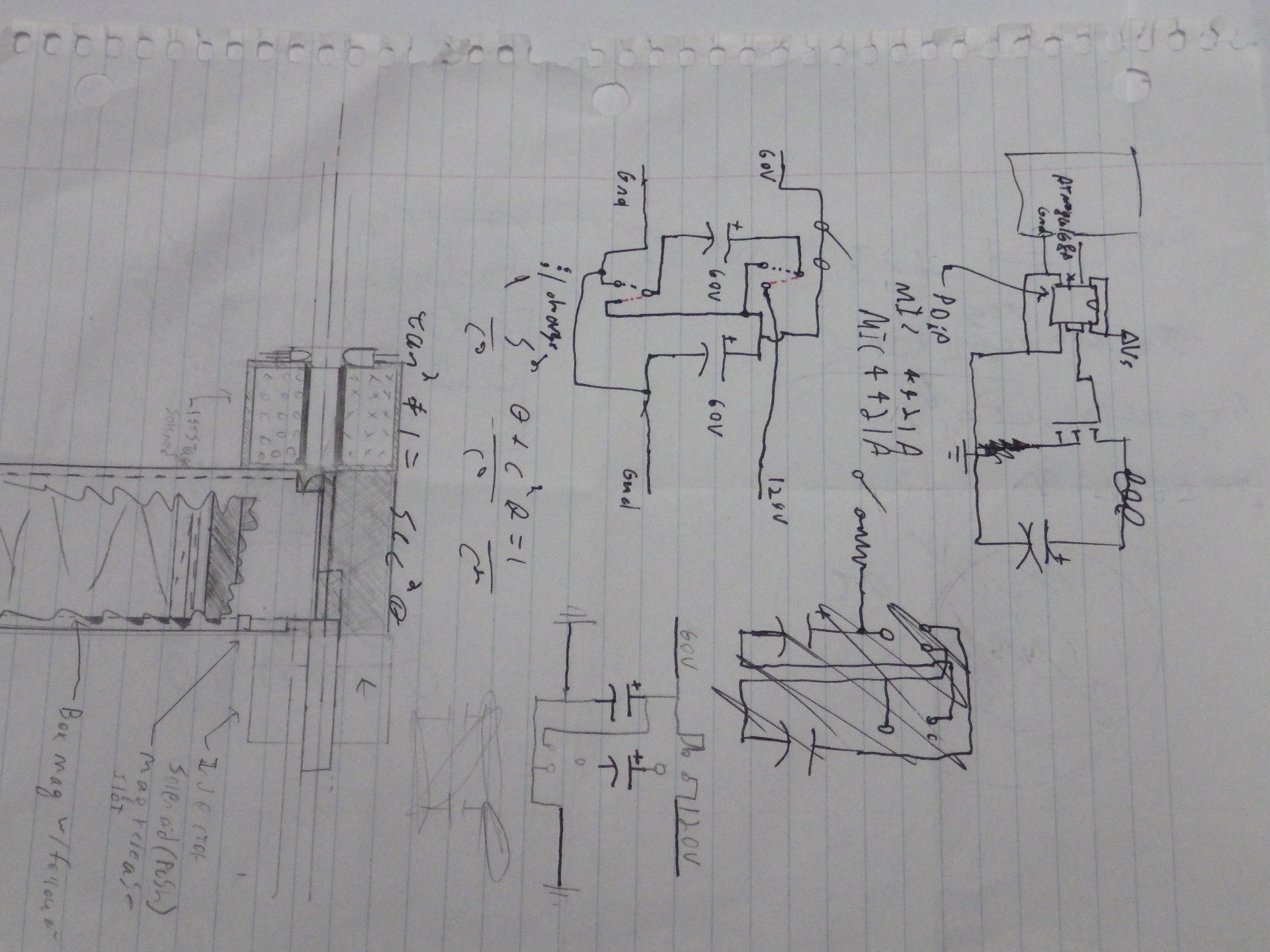
The clarity of the page suffered for having been scrawled on a page of programming notes, but was redrawn later that day. And entirely redone later that week.
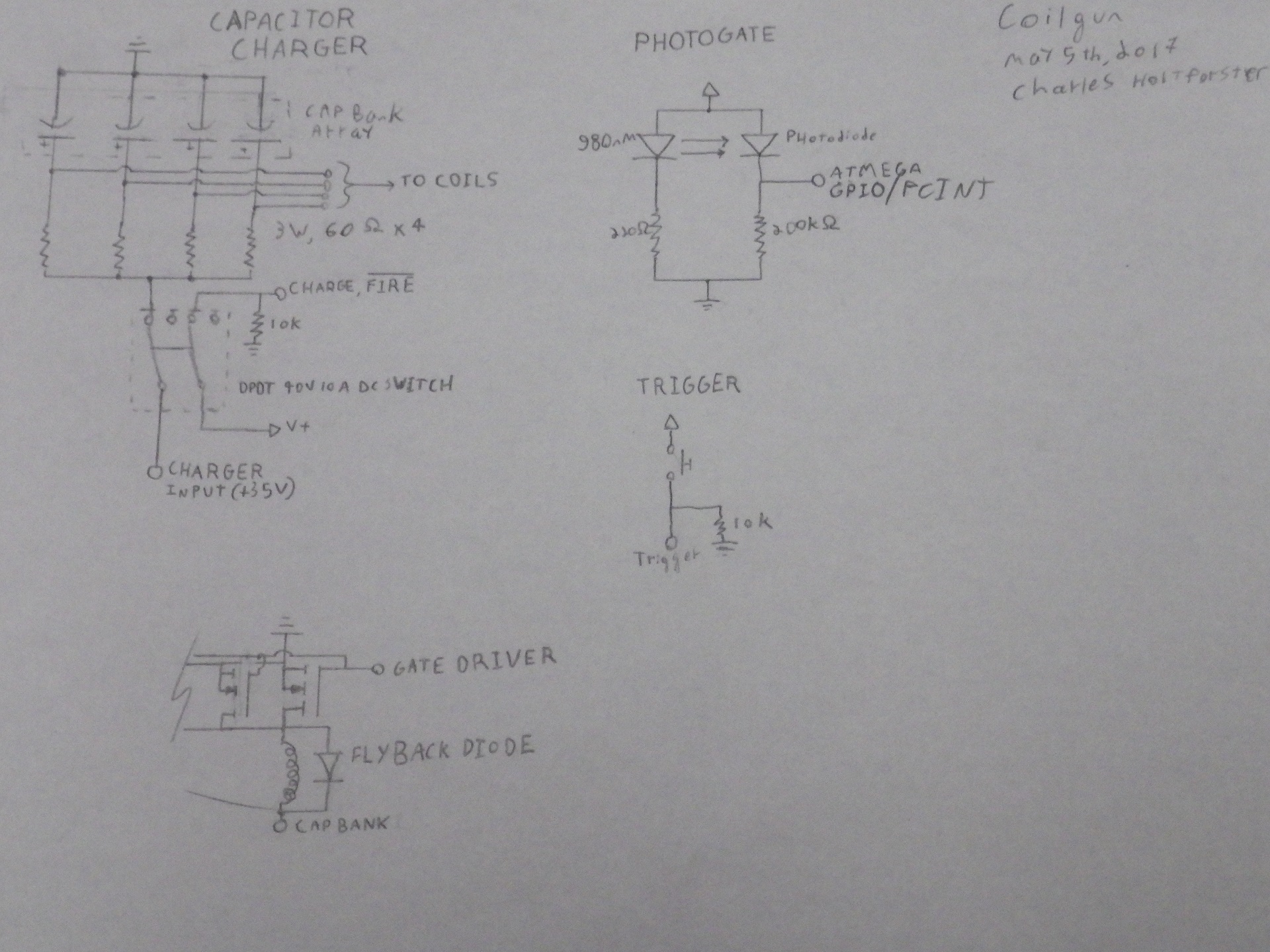
The circuit that was devised was intended to be as simple as possible. A boost converter would take a supply voltage, boost it to 60 volts, and feed it to a capacitor bank through a switch. A large MOSFET would low-side switch the inductor. Photogates (Which previous projects had granted me some experience with) would provide timing feedback to the microcontroller that would control the gate driver that drove the MOSFET.
Before all the parts arrived, some testing was done with the wire and capacitors on hand. At 19 volts, a noteworthy jump could be observed in a coin. When the power supply arrived, coins could be launched with an exciting ringing noise across the room. It was a promising start.
In short order, my DigiKey and Amazon orders arrived, yielding a pile of peculiar electronic components. I chose an IRFP4568PBF MOSFET and a MIC4422A gate driver. The transistor is a rather impressive piece of semiconductor technology, with a maximum pulsed current of 684 amps. The gate driver can drive even a transistor of that size with no difficulty, and can easily manage the 12V switching signal (at 9 amps, no less) while being driven by a feeble yet effective Arduino at 5V.
With the electronics wired up, albeit with alligator clips, more fun was had. Coins could be fired to the ceiling. Timing could be dialed in by computer. But the next step of the design became necssary: Mecahnical optimization.
A 2 inch PVC rod was purchased for the princely sum of $7.75, and converted into the spool shown above. (A note on material choice: PVC on a lathe tends to lead to a Lovecraftian horror of plastic tentacles whippping around at 700 RPM. Metals are more fun, easier, and (arguably) safer, but plastic is quick to machine, and less prone to interfering with magnetic fields, so it was the clear choice.)
After thirty minutes of hand winding the coil, I connected it to the capacitor bank and discharge circuit, and loaded in some lengths of steel rod that had been cut and rounded earlier. The first shot, with a timing of 10 milliseconds, made it to about head height. The second shot, with 8 milliseconds, far surpassed that. At 4 milliseconds, the projectile bounced off the ceiling with a noteworthy thud. This expended roughly 87% of the energy in the eight capacitors (60v, 4400 microfarad as configured, totaling roughly 8 joules) in four milliseconds. This is an input power of 1.3 horsepower, or about a kilowatt. The kinetic energy output is somewhere around a half joule, so the output efficiency is around 6%, which is not bad for an unshielded coil. The remaining energy is lost as heat.
The continuation of the design includes multiple stages with tuned timing, shielding, and photogate triggering, along with a magazine and injector solenoid for more entertaining operation. A friend in Systems Design Engineering pointed out that, clearly, it would be more fun if it had a slide or charging handle on it, so an effort is being made to determine what to use one for, other than a forward assist on the injector solenoid. As this is designed for entertainment in the first place, designing a feed system that was overcomplicated (Closed bolt) for the sake of having a charging handle to "rack" is not beyond reason.
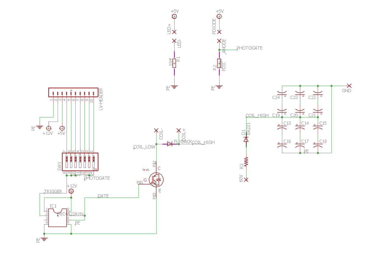
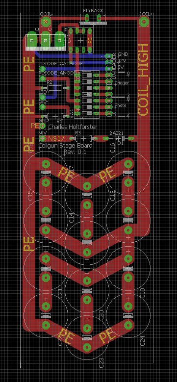
With the basic electrical prototype complete, thought was spared for how to build the final system. Clearly, alligator clips and dead-bug are not a safe method for handling 60V and high slew switching. I'm not a huge fan of being shocked by my experiments, so I fired up EAGLE and made the previous sketches look a touch more legitimate.


The next steps, at this point, were to:
- Decide how to build the prototype mechanical design.
- Design an injector that doesn't require hand-winding a solenoid.
- Build an extended barrel with multiple stages.
- Acquire revision 0.1 board for testing.
The board arrived after a very quick turnaround from the University of Waterloo 3D print centre, and was populated later that day. Even later that day, several components let out the magic smoke.
This cascaded failure took a little while to understand, but here's the play-by-play as I understand it: The flyback diode had too much current pass through it, and shorted itself (smoke-puff number 1), leaving the full blast of the voltage spike to nuke the MOSFET (smoke-puff number 2). This managed to blow the back off the FET, and induced enough voltage in the gate line to destroy the gate driver, too (No smoke, but certain failure). This stopped short of damaging the Arduino driving the gate-driver, and well short of damaging the laptop that was being used to drive the Arduino.
In the process of narrowing down the fault without access to an oscilloscope, several more diodes and transistors were destroyed.
After determining the failure cause and getting through midterms unscathed, I set back to work. A much larger diode was acquired (IDW100E60) from DigiKey, rated for 150 amps. Since the coil has a resistance of 1 ohm, suggesting a current of 60 amps through the flyback diode, this should have plenty of oversizing to prevent future explosions.
Unfortunately, this did not work quite well enough either. The redesigned board managed to hold up to several test firings, before either the MOSFET or diode failed closed, resulting in an exciting flash of light when the rapidly overheating charging circuit was disconnected. One possible source for this mistake is the tool in use, a cheap digtal multimeter. The zero-measurement was not taken into account at first, which is an absolute must in a low-resistance measurements scenario. If the terminals and leads added 0.75 ohms - acceptable in many scenarios - the actual current would be off by a factor of four.